The 100kW Rack Era: How AI Is Rewriting Data Center Power and Cooling From the Ground Up
Your CTO asked a simple question last week: "Can we just add AI racks to our existing data hall?" The answer should have been simple too. But if you've tried to actually spec out GPU dense infrastructure, you know it's not. The moment you cross 30kW per rack, everything breaks. The power distribution that worked fine for traditional compute suddenly becomes a bottleneck. The cooling that kept servers happy starts screaming like a jet engine. The floor layout that maximized every square foot suddenly can't fit the equipment you need.
We've been tracking this transition for two years now, and what we're seeing isn't just higher density compute. It's a complete rewrite of data center infrastructure from the power bus to the CRAH units. The jump from 30kW air cooled racks to 100kW liquid cooled represents the biggest architectural shift in data centers since the move from raised floor to slab on grade.
3.3x Density Jump (30kW to 100kW)The physics are unforgiving. Air cooling hits a hard ceiling around 25 to 30kW per rack, not because the technology stops working, but because the operational costs become insane. Push beyond that limit and you're looking at fan speeds that generate 80+ decibels of noise, power usage effectiveness ratios that make your CFO question your engineering judgment, and cooling infrastructure that consumes more power than the compute it's supposed to support.
Meanwhile, AI workloads don't care about your cooling constraints. NVIDIA's latest GB200 racks are designed for 132kW operation. Cerebras systems are shipping at 180kW. The newest AMD Instinct and Intel Gaudi deployments are routinely hitting 100 to 120kW per rack. We're not talking about peak burst loads or theoretical maximums. These are steady state operational densities for production AI training and inference workloads.
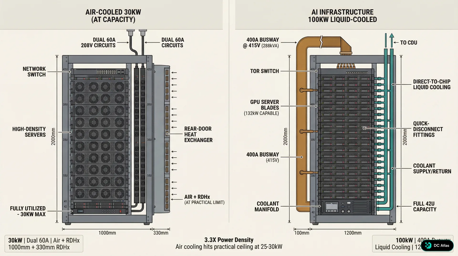
The visual tells the story. On the left, you see the traditional enterprise server rack that has dominated data centers for the past decade. Forty two U of space, dual power feeds, perforated doors for airflow, and maybe 25 to 30kW of actual power draw when fully loaded with high density compute. This design philosophy worked brilliantly for web servers, database clusters, and traditional enterprise applications where compute density was limited by memory capacity and storage requirements rather than raw processing power.
On the right is what AI infrastructure actually looks like. The rack itself is deeper, typically 1200mm instead of the standard 1000mm, because GPU servers need more space for cooling hardware and power distribution. But the real difference isn't visible in the rack itself. It's in the liquid cooling manifolds running overhead, the coolant distribution units taking up floor space, and the completely different power distribution architecture feeding these systems.
The Air Cooling Wall: Why Physics Wins
Every data center engineer learns the same hard lesson eventually. Air is a terrible coolant. It has low thermal conductivity, low heat capacity, and moving it fast enough to cool high density compute requires fans that consume substantial power and generate substantial noise. We've optimized air cooling about as far as physics will allow.
The math is straightforward. Air cooling effectiveness is fundamentally limited by the temperature differential between inlet and outlet air, the volume of air you can move, and the power required to move that air. In a typical data center environment with 75°F supply air temperature and 95°F return air temperature, you're working with a 20°F delta T. To remove 30kW of heat with that temperature differential requires moving roughly 4,500 cubic feet per minute of air through each rack.
That's manageable with conventional server fans and CRAH units. Push the power density to 50kW, and you need 7,500 CFM. At 75kW, you're looking at over 11,000 CFM per rack. The fan power required to move that much air starts consuming a significant percentage of the total facility power. Worse, the acoustic output becomes a workplace safety issue. Server fans running at maximum speed generate 75 to 80 decibels of noise, which exceeds OSHA guidelines for sustained exposure without hearing protection.
80+ dB Noise Level at 30kW+ Air CoolingBut the real killer is power usage effectiveness. As rack densities push beyond 25kW, the power consumed by cooling infrastructure starts growing faster than the power consumed by compute infrastructure. We've seen facilities with high density air cooled deployments hit PUE ratios of 1.6 to 1.8, meaning that for every watt of compute power, they're consuming an additional 0.6 to 0.8 watts for cooling. When hyperscale operators are targeting PUE ratios below 1.1, that level of cooling inefficiency makes high density air cooling economically unviable.
The transition point isn't arbitrary. Our analysis across facilities shows that air cooling remains cost effective up to approximately 25kW per rack in most climates and facility designs. Between 25kW and 30kW, the economics become marginal depending on power costs and cooling infrastructure efficiency. Above 30kW, liquid cooling becomes not just technically superior but economically necessary.
Power Distribution: The Circuit Board to Busway Transition
The shift to 100kW racks breaks traditional power distribution in ways that most engineers don't anticipate. Standard enterprise racks are fed by dual 60 amp circuits at 208V, providing roughly 25kW of available power with N+1 redundancy. That's been the industry standard for traditional compute because it matched the power density that air cooling could handle. But 100kW racks need 288kVA of power capacity, which is almost impossible to deliver through circuit based distribution.
The numbers don't lie. A 100kW rack operating at 415V three phase power requires approximately 170 amps of current per rack. Delivering that through traditional circuit breaker panels would require multiple high amperage circuits per rack, creating a nightmare of cable management, panel space consumption, and failure point multiplication. The installation and maintenance overhead makes circuit based distribution impractical for high density deployments.
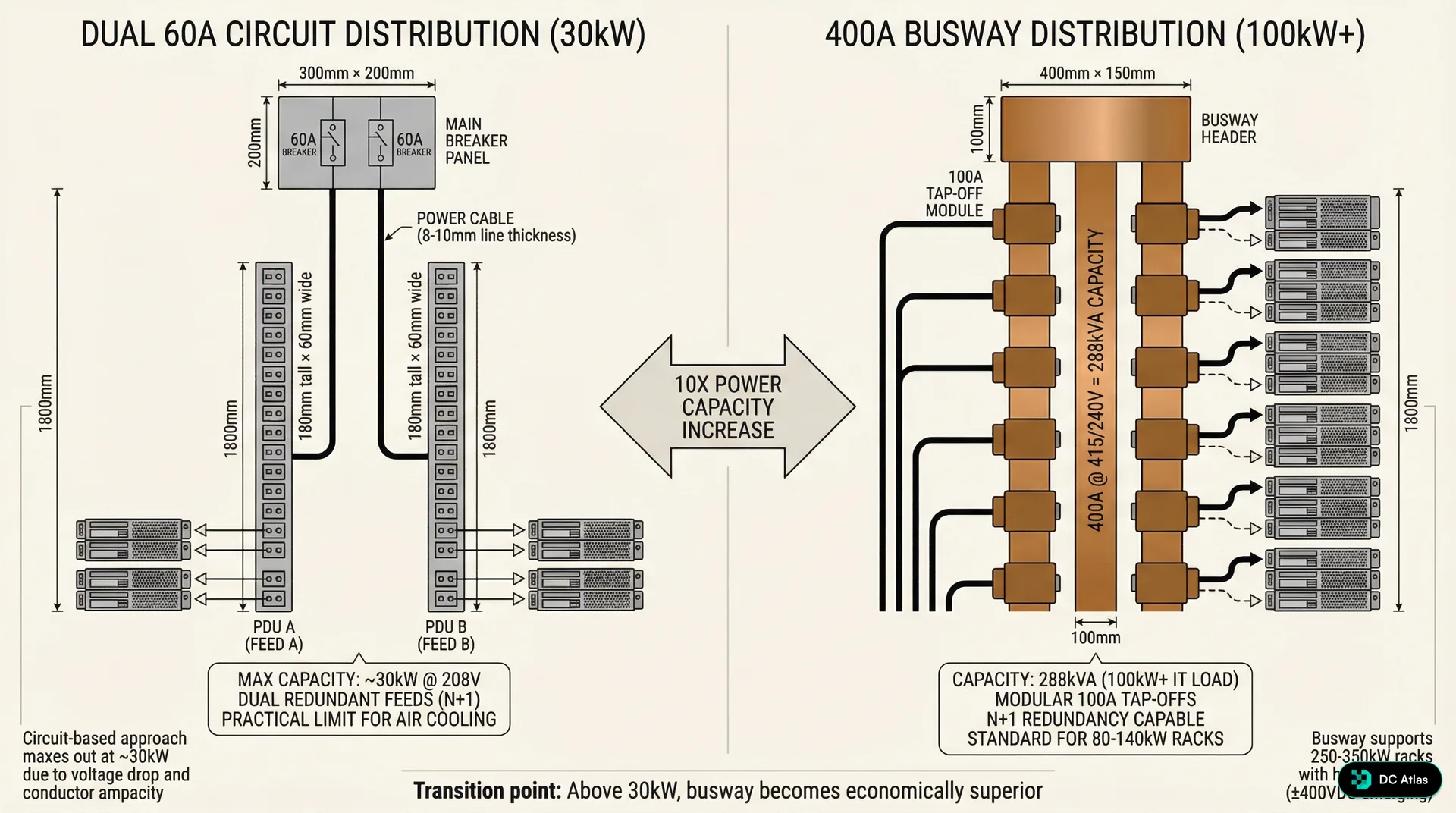
The solution is busway power distribution. Instead of running individual circuits from electrical panels to each rack, busway systems use a continuous power bus that runs along the row of racks with tap off points for individual rack connections. A typical 400 amp busway system can support multiple 100kW racks from a single power run, dramatically simplifying installation and reducing cable overhead.
But busway isn't just about capacity. It's about flexibility and maintainability. Traditional circuit based power distribution locks you into a specific rack power configuration at installation time. If you need to increase power to a rack later, you're running new circuits and potentially upgrading panel capacity. Busway systems allow you to tap off different power levels at different points along the bus, and you can add or modify tap points without shutting down the entire power distribution system.
The economic crossover point is clear from our data. Below 30kW per rack, circuit based distribution is typically more cost effective due to lower upfront infrastructure costs and simpler installation requirements. Above 30kW per rack, busway becomes economically superior due to reduced installation labor, better power utilization efficiency, and lower long term maintenance costs. By the time you're designing for 100kW+ racks, busway isn't just better, it's the only practical option.
400A Typical Busway Capacity for 100kW RacksThe voltage transition is equally important. Traditional data center power distribution operates at 208V because that's what enterprise IT equipment expects. But 100kW racks benefit from higher voltage distribution to reduce current and cable size requirements. Most high density AI infrastructure operates at 415V three phase, which reduces current requirements by roughly 40% compared to 208V distribution for the same power level.
This voltage shift creates interesting challenges for mixed deployments. Facilities supporting both traditional enterprise compute and high density AI workloads need dual voltage distribution infrastructure. Some operators are standardizing on 415V throughout the facility and using rack level transformers for legacy equipment. Others are maintaining separate power distribution systems for different rack types. We're still seeing experimentation with different approaches, and there isn't yet a clear industry consensus on the optimal mixed voltage strategy.
Liquid Cooling: Direct to Chip and Distribution Infrastructure
Liquid cooling for high density racks isn't just about swapping air cooled heat sinks for liquid cooled heat sinks. It's about building an entirely new cooling distribution infrastructure within the data hall. The most common approach for 100kW racks is direct to chip cooling, where liquid coolant is circulated directly to heat sinks mounted on processors, memory modules, and other high power components.
The architecture typically includes coolant distribution units, coolant manifolds, quick disconnect fittings, and redundant coolant supply and return loops. CDUs are essentially liquid cooling equivalent of computer room air handlers. They condition the coolant temperature, maintain proper flow rates and pressure, and provide the interface between rack level cooling loops and facility level cooling infrastructure.
But CDUs aren't just dropped into existing data halls. They require floor space, typically 6 to 8 square feet per 100kW rack they support, which represents roughly 16% footprint overhead in a typical deployment. They need power connections for pumps and controls. They need connectivity to facility cooling water or glycol loops. And they need maintenance access, which affects row layout and aisle width planning.
The coolant distribution itself requires careful engineering. Quick disconnect fittings allow servers to be removed for maintenance without draining coolant from the entire rack, but they introduce potential leak points that don't exist in air cooled systems. Coolant manifolds must be sized to maintain proper flow rates and pressure drops across multiple servers in a rack. And the coolant chemistry must be compatible with all the metals and sealing materials in the cooling loop while providing adequate corrosion protection and thermal performance.
16% CDU Footprint OverheadWe're seeing two primary coolant approaches in production deployments. Facility water based systems use conditioned water or water glycol mixtures as the coolant, typically operating at 45 to 55°F supply temperatures. These systems integrate well with existing facility cooling infrastructure but require careful water treatment and leak management. Dielectric fluid systems use engineered coolants that are electrically non conductive, allowing for direct contact cooling of electronic components. Dielectric systems offer better leak tolerance but typically require dedicated cooling loops that don't integrate with facility water systems.
The performance advantages are substantial. Direct to chip liquid cooling can remove heat flux densities of 100 to 200 watts per square centimeter, which is 5 to 10 times higher than air cooling can handle. More importantly, liquid cooling maintains consistent temperatures across the cooling system, avoiding the hot spots and thermal throttling that plague high density air cooled systems. This thermal consistency allows processors to maintain higher sustained clock speeds, improving actual performance per watt compared to thermally throttled air cooled systems.
Floor Layout Revolution: Aisles, Access, and Infrastructure
The shift to liquid cooled 100kW racks forces a complete rethink of data hall layout. Traditional hot aisle cold aisle configurations were optimized around air flow management and typically used 42 to 48 inch aisle widths to balance floor space utilization with technician access. Liquid cooled deployments need fundamentally different aisle geometries to accommodate CDU placement and maintenance access.
Hot aisles in liquid cooled deployments typically require 60 inch minimum widths, not for airflow but for CDU access and coolant line routing. The CDUs themselves are often positioned within or adjacent to hot aisles to minimize coolant line runs and provide convenient maintenance access. This wider aisle requirement reduces overall rack density per square foot, but the higher power density per rack typically results in higher overall power density per square foot despite the layout inefficiency.
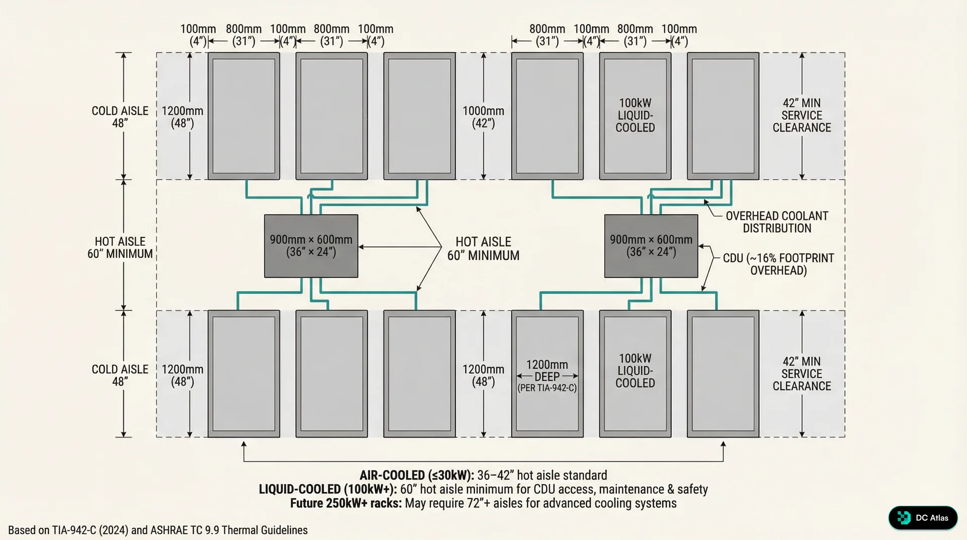
The overhead infrastructure becomes more complex as well. Traditional data centers route power and network cabling overhead, but liquid cooled deployments also require coolant supply and return lines. The coolant lines are typically larger diameter than network cables and require proper slope for air removal and drainage. Overhead coolant distribution also needs isolation valves and service loops to allow maintenance on individual racks without shutting down entire coolant distribution runs.
The interaction between overhead coolant distribution and facility fire suppression systems requires careful coordination. Sprinkler systems must be designed to avoid interference with coolant lines, and coolant lines must be routed to avoid blocking sprinkler coverage patterns. Some facilities are exploring dry pipe or pre action fire suppression systems to reduce the risk of water damage to coolant distribution infrastructure.
Raised floor deployments face additional challenges. Traditional raised floors are designed around air distribution and typically provide 18 to 24 inches of under floor space. Liquid cooled deployments often benefit from slab on grade construction to eliminate the complexity of routing coolant lines through raised floor systems. When raised floor is required, the floor height typically needs to increase to 36 to 42 inches to accommodate coolant distribution infrastructure along with traditional power and network cabling.
The maintenance access requirements are different as well. Air cooled racks primarily need front and rear access for server installation and maintenance. Liquid cooled racks also need access to coolant quick disconnect points, CDU service panels, and coolant manifold isolation valves. This typically requires maintaining clear access zones around CDUs and ensuring that coolant service points are accessible without requiring server removal.
60 inches Minimum Hot Aisle Width for 100kW RacksWe're also seeing changes in row length optimization. Traditional air cooled rows were often designed for 20 to 30 racks per row to optimize cooling air distribution and minimize walking distances for technicians. Liquid cooled rows are often shorter, typically 10 to 15 racks per row, to limit coolant line runs and simplify coolant distribution manifold design. Shorter rows also reduce the impact of coolant system maintenance on overall facility availability.
Standards Evolution: TIA 942 C and ASHRAE Guidelines
The transition to 100kW+ racks is happening faster than industry standards can keep up, but the 2024 updates to key standards are starting to address high density liquid cooled infrastructure. TIA 942 C, released in late 2024, includes specific guidance for liquid cooling distribution systems, coolant containment requirements, and mixed air and liquid cooling deployments.
The updated standard recognizes that liquid cooling isn't a niche application anymore but a mainstream requirement for AI and high performance computing workloads. TIA 942 C provides specific guidance on coolant loop redundancy, CDU placement and sizing, and integration between liquid cooling systems and facility emergency shutdown procedures. Importantly, it also addresses the reliability implications of liquid cooling systems and provides guidance on failure mode analysis and risk mitigation.
ASHRAE Technical Committee 9.9 has been equally aggressive in updating thermal guidelines for liquid cooled systems. The 2024 thermal guidelines recognize that liquid cooled systems operate under fundamentally different thermal constraints than air cooled systems and provide specific guidance on coolant supply temperatures, temperature rise across cooling loops, and thermal monitoring requirements for direct to chip cooling systems.
The ASHRAE guidelines also address the interaction between liquid cooled racks and facility level cooling systems. Unlike air cooled systems where heat rejection is distributed across the data hall through CRAH units, liquid cooled systems concentrate heat rejection at CDUs and coolant heat exchangers. This concentrated heat rejection can create hot spots in facility cooling systems and requires different approaches to cooling system design and control.
Standards Alert
TIA 942 C (2024) now includes specific liquid cooling infrastructure requirements. ASHRAE TC 9.9 updated thermal guidelines for direct-to-chip cooling. Both are essential references for 100kW+ deployments.
The updated standards also recognize the reality of mixed deployments where facilities need to support both traditional air cooled compute and high density liquid cooled AI workloads. The guidance addresses power distribution strategies for mixed voltage requirements, cooling system integration approaches, and fire suppression system design for facilities with both air and liquid cooling systems.
One area where standards are still catching up is coolant system reliability and maintenance requirements. Traditional data center reliability models are built around redundant air cooling systems where individual component failures have limited impact on overall facility availability. Liquid cooling systems introduce different failure modes, including coolant leaks, pump failures, and coolant chemistry issues that don't exist in air cooled systems. The standards are beginning to address these issues, but industry practice is still evolving.
The Performance Reality: Beyond Peak Specifications
The transition to 100kW racks isn't just about cramming more compute into the same footprint. It's about enabling sustained high performance operation that simply isn't possible with air cooling thermal constraints. Most discussions of high density compute focus on peak performance specifications, but the operational reality is that air cooled high performance systems spend significant time in thermal throttling states where performance is reduced to manage heat generation.
We've been tracking actual performance data from both air cooled and liquid cooled high density deployments, and the sustained performance advantages of liquid cooling are more significant than peak performance specifications suggest. GPU systems in particular benefit from consistent thermal conditions because thermal throttling can reduce performance by 15 to 25% when cooling systems can't keep up with peak heat generation.
The thermal consistency of liquid cooling also enables more aggressive performance tuning. Air cooled systems typically need conservative performance settings to avoid thermal throttling during peak load conditions. Liquid cooled systems can operate closer to peak performance specifications because thermal conditions remain more stable across different load conditions.
25% Performance Loss from Thermal ThrottlingThe power efficiency story is equally compelling. While liquid cooling systems require power for coolant pumps and CDU operation, the total facility power efficiency is typically better than high density air cooling because liquid cooling scales more efficiently with load. Air cooling fan power increases dramatically with heat load, while liquid cooling pump power increases much more gradually.
We're seeing PUE improvements of 0.2 to 0.4 when facilities transition from high density air cooling to liquid cooling for equivalent compute loads. For a 10MW facility, that PUE improvement represents 2 to 4MW of reduced cooling power consumption, which translates to substantial operational cost savings and carbon footprint reduction.
The reliability implications are more complex. Liquid cooling systems introduce potential failure modes that don't exist in air cooling, particularly coolant leaks and pump failures. However, liquid cooling systems also eliminate some air cooling failure modes, particularly fan failures and filter clogging that can cause thermal emergencies in air cooled systems.
Our reliability data shows that well designed liquid cooling systems achieve similar overall availability to air cooling systems, but with different failure mode distributions. Liquid cooling failures tend to be more predictable and provide more warning time before critical temperature limits are reached. Air cooling failures can progress more rapidly, particularly fan failures that can cause immediate thermal emergencies.
Future Trajectory: 250kW to Megawatt Class Racks
The 100kW rack standard we're seeing today is just the beginning. Based on our tracking of next generation AI processor roadmaps and cooling technology development, we're projecting continued density increases that will push rack power levels to 140 to 250kW by 2028 and potentially 250 to 900kW by 2030.
The 250kW milestone represents another architectural inflection point. Direct to chip cooling starts hitting practical limits around 200 to 250kW per rack because coolant flow rates and pressure requirements become challenging to manage. Beyond 250kW, we expect to see hybrid cooling approaches combining direct to chip cooling for processors with immersion cooling for memory and support components.
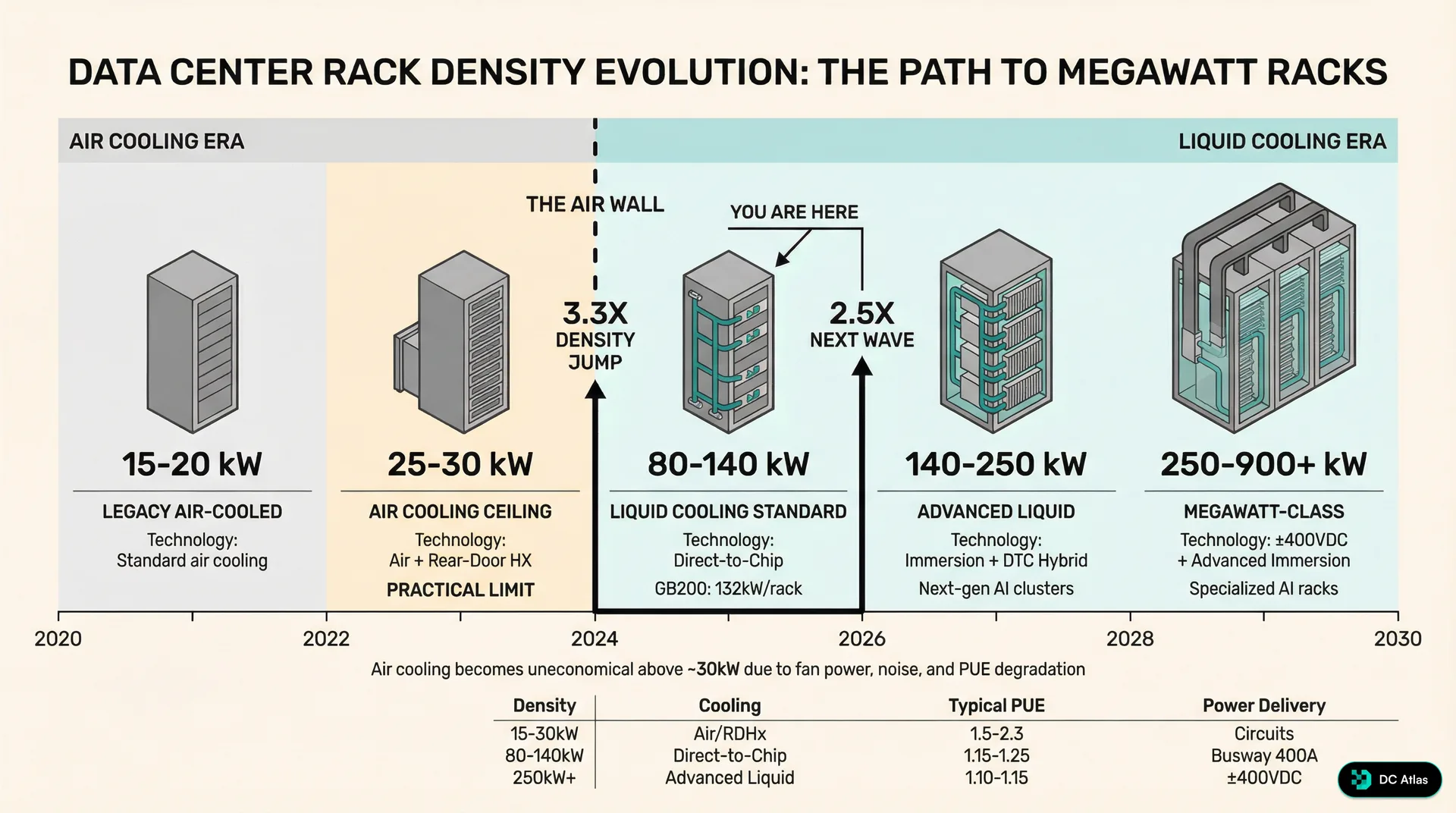
The timeline shows the inflection points clearly. We spent the 2020 to 2023 period optimizing air cooling for traditional enterprise workloads, reaching practical limits around 25 to 30kW per rack. The 2024 to 2026 period is the liquid cooling standardization era, where direct to chip cooling becomes mainstream for AI workloads and 80 to 140kW racks become the new normal.
The 2027 to 2030 period will likely see the emergence of megawatt class racks powered by advanced immersion cooling technologies and 400VDC power distribution systems that eliminate multiple power conversion steps. These systems will require fundamentally different facility designs, potentially moving away from traditional rack and row configurations toward cluster based layouts that optimize for megawatt scale cooling and power distribution.
250 to 900kW Projected Rack Density by 2030The power distribution requirements for megawatt class racks will likely drive adoption of medium voltage distribution systems within data halls. Instead of stepping power down to 415V at building distribution panels, facilities may distribute power at 4160V or higher voltages and step down to utilization voltage at rack or row level transformers. This approach reduces power distribution losses and simplifies high current cable management for extreme density deployments.
The cooling infrastructure for megawatt racks will require integration with district cooling systems or dedicated cooling plants rather than traditional data center HVAC systems. The heat rejection requirements will be similar to small industrial facilities, and the cooling system design will need to optimize for efficiency at much higher heat flux densities than current liquid cooling systems handle.
Economic Implications: The Total Cost Shift
The transition to 100kW racks fundamentally changes data center economics in ways that extend far beyond cooling and power infrastructure costs. The higher density allows operators to deliver more compute capacity per square foot of data hall space, which improves revenue density for colocation providers and reduces real estate costs for enterprise operators.
But the infrastructure costs are front loaded. Converting existing facilities to support 100kW racks typically requires significant power and cooling infrastructure upgrades that can cost $2,000 to $4,000 per kW of additional capacity. New construction designed from the ground up for high density liquid cooling is more cost effective, typically adding 15 to 25% to total facility construction costs compared to traditional air cooled designs.
The operational cost equation depends heavily on power costs and cooling efficiency. In markets with high electricity costs, the improved PUE of liquid cooling systems provides substantial ongoing savings that can justify the higher infrastructure costs within 3 to 5 years. In markets with low electricity costs, the payback period extends to 5 to 8 years, making the economic case more marginal for existing facility conversions.
$2,000-$4,000 Retrofit Cost per kW of 100kW CapacityThe maintenance cost structure is different as well. Liquid cooling systems require different technical skills and spare parts inventory compared to air cooling systems. Coolant chemistry monitoring and management adds ongoing operational overhead that doesn't exist with air cooling. However, liquid cooling systems typically have fewer mechanical components than high density air cooling systems, which can reduce overall maintenance requirements once operators develop the appropriate technical capabilities.
The reliability risk profile shifts as well. Air cooling system failures typically affect individual racks or small groups of racks. Liquid cooling system failures can potentially affect larger numbers of racks if coolant distribution systems are shared across multiple racks. This risk profile requires different approaches to redundancy and emergency response procedures.
We're seeing most operators address reliability concerns through modular cooling system designs where individual CDUs support no more than 4 to 6 racks, limiting the impact of individual cooling system failures. Operators are also implementing enhanced monitoring systems that provide early warning of coolant temperature, flow rate, and chemistry issues before they result in cooling system failures.
Implementation Roadmap: Making the Transition
For operators considering the transition to 100kW racks, the implementation approach depends heavily on existing facility capabilities and timeline requirements. Facilities with adequate electrical service capacity and modern cooling plants can often support 100kW racks with focused infrastructure upgrades. Older facilities may require more extensive electrical and cooling infrastructure investment that makes new construction more economical.
The typical upgrade path starts with power distribution. Existing facilities need assessment of electrical service capacity, transformer capacity, and distribution panel capacity to determine what level of power distribution upgrade is required. Most facilities require at least busway installation and may require transformer upgrades or electrical service upgrades depending on existing capacity margins.
Cooling infrastructure assessment is equally critical. Facilities with central cooling plants typically have adequate facility level cooling capacity to support 100kW racks, but may need cooling distribution infrastructure upgrades to support CDU installation and coolant distribution. Facilities with packaged HVAC systems typically need cooling plant upgrades to support liquid cooling heat rejection requirements.
Planning Reality Check
Budget 12 to 18 months for high density infrastructure upgrades in existing facilities. Power utility coordination alone can take 6 to 9 months in many markets.
The timeline for infrastructure upgrades is typically longer than operators expect. Electrical utility coordination for service upgrades can take 6 to 12 months depending on utility capacity and local permitting requirements. Major cooling infrastructure upgrades typically require 6 to 9 months for equipment procurement and installation. Overall project timelines of 12 to 18 months are common for significant facility upgrades.
New construction offers more design flexibility and typically faster deployment timelines. Facilities designed from the ground up for 100kW racks can optimize power distribution routing, cooling infrastructure placement, and floor layouts for high density operations. New construction timelines are typically 18 to 24 months from design start to operational readiness, which is comparable to traditional data center construction timelines despite the additional infrastructure complexity.
The operational readiness requirements are different as well. Staff need training on liquid cooling system operation and maintenance procedures. Spare parts inventory needs to include coolant system components and coolant chemistry management supplies. Emergency response procedures need updates to address potential coolant leaks and cooling system failures.
Most operators are approaching the transition incrementally, starting with pilot deployments of 100kW racks in dedicated areas of existing facilities or dedicated zones in new facilities. This approach allows operators to develop operational experience with liquid cooling systems while limiting risk exposure during the learning curve period.
The 100kW rack era represents more than just higher density compute. It's a fundamental shift in data center architecture that touches every aspect of facility design and operation. The organizations that understand this shift and begin planning for it now will be positioned to support the next generation of AI and high performance computing workloads. Those that don't may find themselves constrained by infrastructure that can't adapt to the demands of modern compute.
Join the waitlist to access premium features
Get access to 7,000+ data center facilities, AI-powered search, and market intelligence.
Join Waitlist